How To Make A Flowchart In Microsoft Word

In this article you’ll learn what the basic symbols in flowcharts mean, and how to draw out these flowcharts in Microsoft Word.
In nearly every industry, people use flowcharts as part of troubleshooting, decision-making, and logical analysis.
If you learn how to make a flowchart in Microsoft Word, you’ll always have a tool at your disposal to do these kinds of thought experiments.
In this article, you’ll learn what the basic symbols in flowcharts mean, and how to draw out these flowcharts in Microsoft Word. If you already understand basic flowcharting, you can skip down to the section on how to make a flowchart in Word.
Basic Flowchart Symbols
Before you can draw out flowcharts in Word, it’s important to understand what those symbols mean.
The following simple guide will help with using the right symbols at the right time.
Start or Terminator

The oval block is known as the “terminator”. No, not the kind of terminator that saves the planet. This terminator is the kind you use to terminate a logical flowchart branch. It’s used to start the flowchart as well.
Step Blocks

The step block is one of the most common shapes used when you’re writing flowcharts. It represents a step where some process or work is done. For example, if you’re writing code that includes a module that’ll calculate something based on user input, you’d use a process block to represent “Calculate User Results”.
Decision Blocks

Frequently, in a flowchart logic flow, the process needs to make a logical decision. This is usually based on inputs, represented by the line or lines flowing into the top of the decision block. The decision then generates outputs based on the outcome of the logic, represented by lines flowing out of the bottom of the sides of the decision block.
Input/Output Data Blocks

There are a variety of blocks used to represent data that flows into and out of your flowchart processes. The most common ones are those displayed above. These include:
- Input/Output: Trapezoid blocks like the one on the left. This could be output from a process calculation block or an input from some other process in the flowchart.
- Manual Input: User input trapezoid for something like input from an entry form.
- General Data Storage: The shape displayed on the right is a general data storage block representing data you might write to some file or database.
There are also specific shapes for things like databases, documents, or internal storage. You can also find those in the Microsoft Word collection of flowchart shapes.
Miscellaneous Shapes

There are a few other common shapes you need to know before heading into Word to create your first flowchart. These include:
- Off-Page Connector: Allows you to continue your flowchart onto another page by pointing to the label for the start of the second-page flowchart here.
- Predefined Process: Reference a process block you’ve defined elsewhere that you want to reuse in this spot.
- Merge: Combine the output of two other flowchart lines into a single process using the Merge triangle.
You typically connect flowchart shapes with a line that terminates with an arrow. You can use any kind of line type, so long as you’re consistent with it throughout the entire flowchart.
Make a Flowchart in Microsoft Word
Now that you know the basic, most common flowchart symbols, you’re ready to make your own flowchart in Microsoft Word. The purpose of the example flowchart we’ll discuss here is to write a program to take manual input from a user form. The program will be used in a liquor store to allow customers to automatically confirm their legal ability to purchase alcohol.
The user will type their name and social security number into the form on the screen. Your program will look up their information from a database to obtain their age. If they’re over 21, the program will process their purchase for alcohol and output a receipt. If they’re under 21, it will display an error screen saying that they’re too young to purchase alcohol.
Let’s get started.
Start Flowchart with Manual Entry
Open Microsoft Word and select the Insert menu. Select the Shapes dropdown to view all available flowchart shapes.
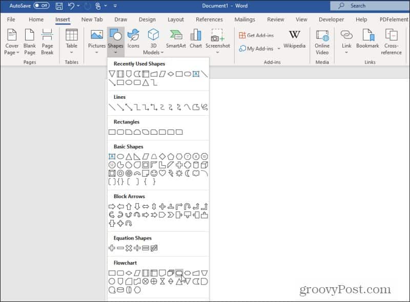
Look for and select the Terminator shape. Remember, the Terminator shape is also the one used to start a flowchart.
Draw the shape at the top of the Word page, and set the fill and outline coloring however you like. Right-click the shape and choose Add Text to enter text inside the shape.
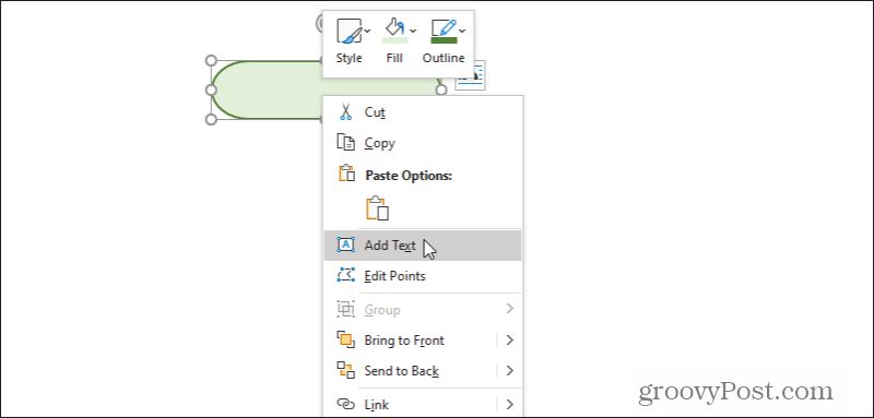
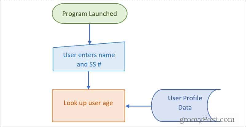
Type something like “Program Launched” or even just “Start” for the text in this block.
Next, you’re going to want a block for user input. Select the Insert menu, select Shapes, and choose the manual input shape. Draw this into the Word document just under the start block. Right-click, select Edit Text and type the appropriate text to describe the manual data entry.
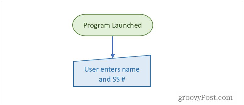
Draw a line with an arrow (using the same Insert menu), and format the line to whatever thickness you prefer.
Next, you’ll need to have the process deal with the newly entered data.
Processing Data In Flowcharts
In the next step of your flowchart, you’ll want to manage entered data. This will require a process block.
Use the Insert menu and choose the Process block. Place it underneath the data entry and add an arrow line.
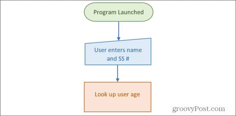
For this process to work properly, the process block needs to obtain the user’s age (based on name and SS# input) from a database. You could use either the special “database” block or the more generic General Data Storage block described above.
Add this block to the side of the process block and draw an arrow from it to the process block.
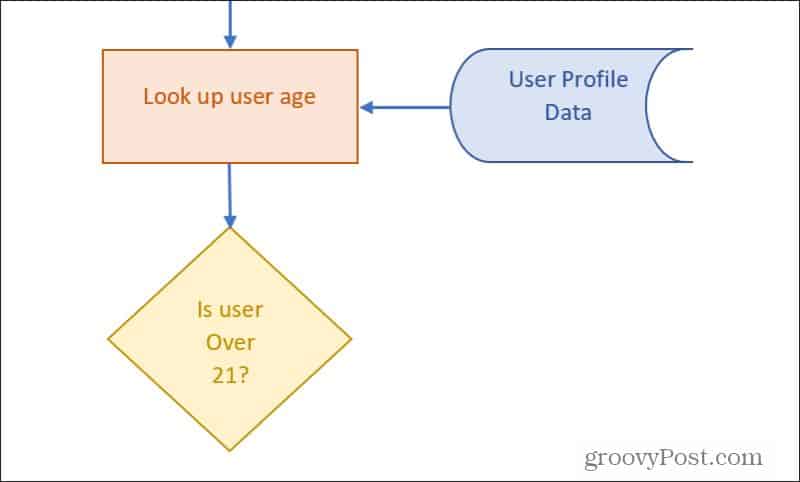
Now that the process has the right inputs, you’ll need to draw a process output line out of the bottom of the process. Typically a process needs to make a decision, such as in this case. So the next step of your flowchart will be the decision block.
Decision Blocks In a Word Flowchart
Draw the diamond decision block (from the Insert menu) right under the process block. Add text that describes the decision that the process needs to make.
As always, draw an arrow from the bottom of the process block down to the decision block.
As mentioned previously, decision blocks receive input. You’ll have an output for every possible result. In this case, there will be output for YES and one for NO.
Technically, this decision will be made inside the program. Decision blocks often represent process decisions, so typically almost always follow process blocks.
Draw a line with an arrow as an output from the bottom of the triangle. Label this line YES. Draw an angled line from the side of the decision block and label it NO. You can create the labels by adding a text box without a borderline.

Next, you’ll need to provide the logical flow on each output of the decision block.
Finishing Your Flowchart in Microsoft Word
Now you can just continue the process of building the rest of your flowchart using whatever flowchart blocks make the most sense.
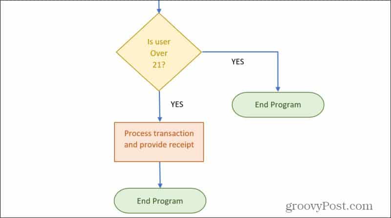
You can use either the Off-Page Connector block to continue any process flow onto another page. Or use the Terminator block to finish any logic lines in the flowchart.
Making Flowcharts in Word Is Easy
As you can see, making a flowchart in Word doesn’t have to be complicated. Word also provides all of the important logical blocks you need to create mostly any flowchart.
You can use flowcharts to brainstorm ideas, work through important decisions, or like in this example chart out the logic of your programming projects.
If you don’t want to use Word, there are plenty of other tools available to draw diagrams and flowcharts as well.
And if you’re running an old version of Word check out our article on how to make a flow chart in Word 2007.